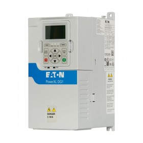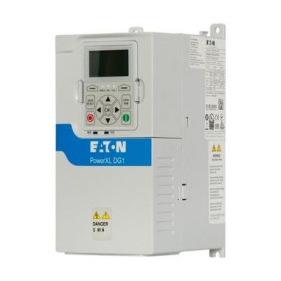

Eaton DG1 Variable frequency drive, 400 V AC, 3-phase, 3.3 A, 1.1 kW
Eaton DG1 Variable frequency drive, 400 V AC, 3-phase, 3.3 A, 1.1 kW, IP20/NEMA0, Brake choppe
COSTURILE LOCALE DE TRANSPORT SUNT DE 30 RON FARA TVA
General specifications
| Product Name |
Eaton DG1 variable frequency drive
|
| Catalog Number |
9702-0201
|
| EAN |
4015081939640
|
| Product Length/Depth |
173.5 mm
|
| Product Height |
268.7 mm
|
| Product Width |
127 mm
|
| Product Weight |
2.2 kg
|
| Certifications |
CE
Safety requirements: IEC/EN 61800-5 UL File No.: E134360 EAC UL Category Control No.: NMMS, NMMS7 Specification for general requirements: IEC/EN 61800-2 IEC/EN 61800-3 UL CUL C-Tick RoHS, ISO 9001 UkrSEPRO |
| Catalog Notes |
The brake resistors are assigned based on the maximum rated power of the variable frequency drive. Additional brake resistors and designs (e.g. different duty cycles) are available upon request.
|
| Model Code |
DG1-343D3EB-C20C
|
Features & Functions
| Features |
Tool-less swapping of fan
Temperature-controlled fan Parameterization: Fieldbus Parameterization: Keypad Parameterization: Power Xpert inControl |
| Functions |
4-quadrant operation possible
|
General
| Air volume capacity |
24 m³/h
|
| Cable length |
100 m, screened, maximum permissible, Motor feeder
C3 ≤ 50 m, Radio interference level, maximum motor cable length C2 ≤ 10 m, Radio interference level, maximum motor cable length |
| Degree of protection |
IP20
NEMA Other |
| Electromagnetic compatibility |
1st and 2nd environments (according to EN 61800-3)
|
| Environmental class |
3C2, 3S2 (Air quality)
|
| Fitted with: |
Internal DC link
Radio interference suppression filter Additional PCB protection Multi-line graphic display DC link choke Brake chopper IGBT inverter Breaking resistance Control unit PC connection |
| Frame size |
FS0
|
| Mounting position |
Vertical
|
| Number of slots |
2 (expansion)
|
| Overvoltage category |
III
|
| Pollution degree |
2
|
| Product Category |
Variable frequency drives
|
| Protection |
Finger and back-of-hand proof, Protection against direct contact (BGV A3, VBG4)
|
| Radio interference class |
Optional external radio interference suppression filter for longer motor cable lengths and for use in different EMC environments
C1: with external filter, for conducted emissions only C2, C3: depending on the motor cable length, the connected load, and ambient conditions. External radio interference suppression filters (optional) may be necessary. |
| Safety function/level |
STO (Safe Torque Off, SIL1, PLc Cat 1)
|
| Shock resistance |
Mechanical, According to EN 61800-5-1, IEC/EN 60068-2-27
UPS drop test (for weights inside the UPS frame) Storage and transportation: maximum 15 g, 11 ms (inside the packaging) |
| Suitable for |
Branch circuits, (UL/CSA)
|
| Vibration |
Resistance: 5 - 15.8 Hz, Amplitude 1 mm (peak)
Resistance: 5 - 150 Hz, According to EN 61800-5-1, IEC/EN 60068-2-6 Resistance: 15.8 – 150 Hz, 1 g, Maximum acceleration amplitude |
Climatic environmental conditions
| Altitude |
Max. 1000 m
Above 1000 m with 1 % derating per 100 m Max. 3000 m Max. 2000 m for Corner Grounded TN Systems |
| Ambient operating temperature - min |
-10 °C
|
| Ambient operating temperature - max |
50 °C
|
| Ambient operating temperature at 150% overload - min |
-30 °C
|
| Ambient operating temperature at 150% overload - max |
50 °C
|
| Ambient storage temperature - min |
-40 °C
|
| Ambient storage temperature - max |
70 °C
|
| Climatic proofing |
< 95 average relative humidity (RH), no condensation, no corrosion
|
Main circuit
| Current limitation |
0.1 - 2 x IH (CT), motor, main circuit
|
| Efficiency |
97.33 % (η)
|
| Heat dissipation at current/speed |
27 W at 25% current and 0% speed
30 W at 25% current and 50% speed 31 W at 100% current and 50% speed 35 W at 50% current and 50% speed 38 W at 50% current and 90% speed 42 W at 100% current and 0% speed 46 W at 50% current and 0% speed 52 W at 100% current and 90% speed |
| Input current ILN at 110% overload |
5.5 A
|
| Input current ILN at 150% overload |
4.3 A
|
| Leakage current at ground IPE - max |
0.2 mA
|
| Mains current distortion |
35.3 %
|
| Mains switch-on frequency |
Maximum of one time every 60 seconds
|
| Mains voltage - min |
380 V
|
| Mains voltage - max |
500 V
|
| Operating mode |
U/f control
Sensorless vector control (SLV) Speed control with slip compensation Torque regulation |
| Output frequency - min |
0 Hz
|
| Output frequency - max |
400 Hz
|
| Output voltage (U2) |
500 V AC, 3-phase
400 V AC, 3-phase 480 V AC, 3-phase |
| Overload current IL at 110% overload |
4.73 A
|
| Overload current IL at 150% overload |
4.95 A
|
| Rated conditional short-circuit current (Iq) |
100 kA
|
| Rated control supply voltage |
10 V DC (Us, max. 10 mA)
|
| Rated frequency - min |
45 Hz
|
| Rated frequency - max |
66 Hz
|
| Rated operational current (Ie) at 110% overload |
4.3 A
|
| Rated operational current (Ie) at 150% overload |
3.3 A
|
| Rated operational power at 380/400 V, 50 Hz |
1.1 kW
|
| Rated operational power at 380/400 V, 50 Hz, 110% overload |
1.5 kW
|
| Rated operational power at 500 V, 50 Hz |
1.5 kW
|
| Rated operational power at 500 V, 50 Hz, 110% overload |
2.2 kW
|
| Rated operational voltage |
480 V AC, 3-phase
400 V AC, 3-phase 500 V AC, 3-phase |
| Resolution |
0.01 Hz (Frequency resolution, setpoint value)
|
| Short-circuit protection rating |
10 A, UL (Class CC or J), Safety device (fuse or miniature circuit-breaker), Power Wiring
|
| Starting current - max |
200 %, IH, max. starting current (High Overload), For 2 seconds every 20 seconds, Power section
|
| Supply frequency |
50/60 Hz
|
| Switching frequency |
4 kHz, 1 - 12 kHz adjustable, fPWM, Power section, Main circuit
|
| System configuration type |
TN-S, TN-C, TN-C-S, TT, IT
|
| Voltage rating - max |
500 VAC
|
Motor rating
| Assigned motor current IM at 400 V, 50 Hz, 110% overload |
3.6 A
|
| Assigned motor current IM at 400 V, 50 Hz, 150% overload |
2.6 A
|
| Assigned motor current IM at 440 - 480 V, 60 Hz, 150% overload |
3 A
|
| Assigned motor current IM at 440/480 V, 60 Hz, 110% overload |
3.4 A
|
| Assigned motor current IM at 500 V, 50 Hz, 110% overload |
4 A
|
| Assigned motor current IM at 500 V, 50 Hz, 150% overload |
2.9 A
|
| Assigned motor power at 460/480 V, 60 Hz |
1.5 HP
|
| Assigned motor power at 460/480 V, 60 Hz, 110% overload |
2 HP
|
Apparent power
| Apparent power at 400 V |
3 kVA
|
| Apparent power at 480 V |
3.7 kVA
|
Braking function
| Braking resistance |
63 Ω
|
| Braking torque |
Adjustable to 150 % (I/Ie), DC - Main circuit
Max. 100 % of rated operational current Ie with external braking resistor - Main circuit Max. 30 % MN, Standard - Main circuit Adjustable to 150 %, DC - Main circuit |
| Switch-on threshold for the braking transistor |
850 VDC
|
Control circuit
| Number of inputs (analog) |
2
|
| Number of inputs (digital) |
8
|
| Number of outputs (analog) |
2
|
| Number of outputs (digital) |
1
|
| Number of relay outputs |
3 (parameterizable, 2 changeover contacts and 1 N/O, 6 A (240 V AC) / 6 A (24 V DC))
|
| Rated control voltage (Uc) |
24 V DC (external, max. 250 mA options incl.)
|
Communication
| Communication interface |
BACnet MS/TP, built in
PROFIBUS, optional SmartWire-DT, optional Modbus TCP, built in Ethernet IP, built in CANopen®, optional Modbus RTU, built in DeviceNet, optional |
| Connection to SmartWire-DT |
In conjunction with DXG-NET-SWD SmartWire DT module
Yes |
| Protocol |
BACnet
CAN DeviceNet EtherNet/IP MODBUS Other bus systems PROFIBUS PROFINET IO TCP/IP |
Design verification
| Equipment heat dissipation, current-dependent Pvid |
61 W
|
| Rated operational current for specified heat dissipation (In) |
3.3 A
|
| Static heat dissipation, non-current-dependent Pvs |
11.4 W
|
| 10.2.2 Corrosion resistance |
Meets the product standard's requirements.
|
| 10.2.3.1 Verification of thermal stability of enclosures |
Meets the product standard's requirements.
|
| 10.2.3.2 Verification of resistance of insulating materials to normal heat |
Meets the product standard's requirements.
|
| 10.2.3.3 Resist. of insul. mat. to abnormal heat/fire by internal elect. effects |
Meets the product standard's requirements.
|
| 10.2.4 Resistance to ultra-violet (UV) radiation |
Meets the product standard's requirements.
|
| 10.2.5 Lifting |
Does not apply, since the entire switchgear needs to be evaluated.
|
| 10.2.6 Mechanical impact |
Does not apply, since the entire switchgear needs to be evaluated.
|
| 10.2.7 Inscriptions |
Meets the product standard's requirements.
|
| 10.3 Degree of protection of assemblies |
Does not apply, since the entire switchgear needs to be evaluated.
|
| 10.4 Clearances and creepage distances |
Meets the product standard's requirements.
|
| 10.6 Incorporation of switching devices and components |
Does not apply, since the entire switchgear needs to be evaluated.
|
| 10.7 Internal electrical circuits and connections |
Is the panel builder's responsibility.
|
| 10.8 Connections for external conductors |
Is the panel builder's responsibility.
|
| 10.9.2 Power-frequency electric strength |
Is the panel builder's responsibility.
|
| 10.9.3 Impulse withstand voltage |
Is the panel builder's responsibility.
|
| 10.9.4 Testing of enclosures made of insulating material |
Is the panel builder's responsibility.
|
| 10.10 Temperature rise |
The panel builder is responsible for the temperature rise calculation. Eaton will provide heat dissipation data for the devices.
|
| 10.11 Short-circuit rating |
Is the panel builder's responsibility. The specifications for the switchgear must be observed.
|
| 10.12 Electromagnetic compatibility |
Is the panel builder's responsibility. The specifications for the switchgear must be observed.
|
| 10.13 Mechanical function |
The device meets the requirements, provided the information in the instruction leaflet (IL) is observed.
|

Politica de retur
Transport
Putem livra practic prin curier la orice adresa din Romania. Rețineți că există restricții pentru unele produse, iar unele produse nu pot fi expediate către destinații internaționale.